Dimension
Dimensions sketch entities, and model edges or vertices, with the kind of dimension the selection and the placement call for.
Sketch tab > Dimension, press D in a sketch, or right-click in the graphics area > Dimension. With no sketch open, it starts the Sketch command first.
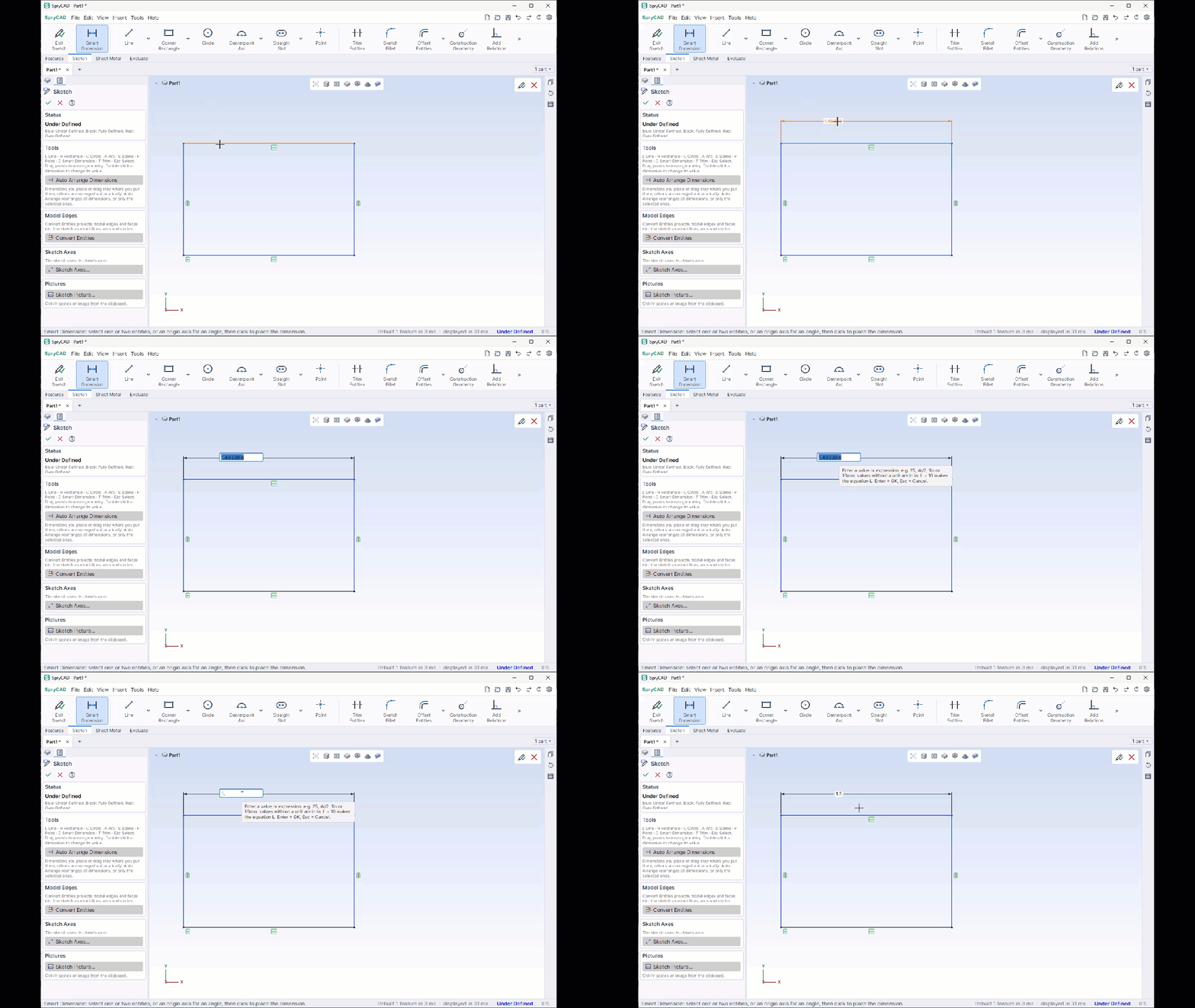
Adding a Dimension
- Click Dimension.
- Select one or two entities or points. A preview of the dimension follows the pointer.
- Click where the value goes. The value box opens at the label.
- Type the value and press Enter.
After one selection, clicking another entity or point adds it as the second; clicking empty space places the dimension. After two selections, the next click places it. Press Esc to drop the selections.
Dimension Kinds
| Selection | Dimension |
|---|---|
| A circle | Diameter (⌀) |
| An arc | Radius (R) |
| A spline | Length along the curve (L) |
| A line | Length |
| Two points | Distance between them |
| Two circles or arcs, or a point and a circle or arc | Distance between centers |
| A point, circle or arc, and a line | Distance from the point or center to the line |
| Two parallel lines | Distance between them |
| Two lines that are not parallel | Angle |
For a slanted line, or two points not level or plumb, where you place the value sets what is measured:
| Value placed | Measures |
|---|---|
| Above or below, within their width | Horizontal distance |
| Beside, within their height | Vertical distance |
| Anywhere else | True distance |
An angle measures the sector the value is placed in.
Dimensions to the Model and the Origin
When no sketch geometry is under the pointer, a model vertex or edge, or a point, line or circle of another sketch shown, can be selected. It is added to the sketch as reference geometry and follows the model or that sketch. A circular edge selected near its center gives its center. An edge perpendicular to the sketch plane cannot be used.
The red axis lines at the sketch origin can be selected as lines, for example for an angle to the horizontal.
Diameters to a Centerline
A distance between a centerline and a point, or a line parallel to it, is a diameter (⌀, twice the distance) when the value is placed across the centerline from the geometry. Placed on the geometry's side, it is the distance. Use it to dimension a profile for a revolve. Dragging the value across the centerline changes it from one to the other, and the number changes so the geometry stays put. A dimension whose value is an equation stays as it is.
This works only with construction lines. A distance to a solid line is always a distance.
The Value Box
The box opens when a dimension is placed, and when you double-click a dimension. Enter applies the value, Esc cancels, and clicking elsewhere applies it.
The value accepts:
| Entry | Example |
|---|---|
| A number, in the part's units | 25 |
| A number with a unit | 1in, 10mm |
| An equation of variables and numbers | W/2, W/2 + 5mm |
| A new variable | L = 10 |
L = 10 creates the variable L with that value, and the dimension is driven by L. The variable is added to the
part's equations when you click Exit Sketch, in the same undo step as the sketch. Names of the part's variables
are suggested as you type.
A value with its own unit shows in that unit, such as 1in in a millimeter part. A length or radius must be greater
than zero. A horizontal or vertical distance can be negative.
The first dimension you set in a sketch scales everything drawn so far, so the shape keeps its proportions. It scales about the origin when the sketch is tied to it, else about the middle of the sketch. This is skipped when the sketch has fixed points, such as model references. The first length typed while drawing scales the same way, so the shape keeps its size on screen.
If the sketch cannot be solved with the value, the status bar says so and the sketch shows Over Defined.
How Dimensions Show
| Label | Meaning |
|---|---|
⌀20, R5, L 40 |
Diameter, radius, spline length |
(25) in gray |
A driven dimension |
W = 20 |
Driven by the variable W |
W/2 = 10 |
Its own equation, when short |
Σ 10 |
An equation too long to show |
A selected dimension shows in blue, and one under the pointer in orange.
Dimensions you place or drag stay where you put them. The others are arranged automatically clear of each other and of the geometry. Auto Arrange Dimensions on the sketch page arranges all dimensions, or the selected ones, automatically again.
Driven Dimensions
A driven dimension reports a value and does not control the geometry. A dimension that would over-define the sketch is added as a driven dimension, and the status bar says so.
To make a dimension driven, or driving again, select it and set Driven (reference) in the Dimension section of the sketch page. Double-clicking a driven dimension does not open the value box.
Dimension Section
Shown on the sketch page when one dimension is selected.
- Value
- The dimension's value or equation. Applied on Enter or when you leave the field.
- Edit Value…
- Opens the value box on the dimension in the graphics area.
- Driven (reference)
- The dimension reports its value instead of controlling the geometry.
- Reverse Direction
- For the distance of an offset made by Offset Entities: puts the offset on the other side.
Each dimension is named D1, D2 and so on, in the order placed. The Selected Entities section lists it as its name and value.
Editing a Dimension
- Double-click it, with no drawing tool active, to open the value box.
- Select it and change Value in the Dimension section.
- Drag its value to move the label.
- Select it and press Del to delete it.