Sketch
Draws the 2D profiles, paths and positions that features are built from, on a plane or planar face.
Sketch tab > Sketch, or right-click a plane or planar face > Sketch.
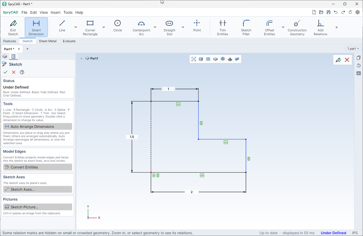
Starting a Sketch
- Select a plane or planar face in the graphics area or the design tree.
- Click Sketch. The view turns normal to the plane, its X axis to the right, and the Sketch tab shows its tools.
- Draw the entities, then add dimensions and relations.
- Click Exit Sketch.
With nothing selected, Sketch opens the Edit Sketch page and shows the planes, even hidden ones. Select a default plane, reference plane or planar face to start the sketch on it. If the last feature is a reference plane that nothing uses yet, it is already in the Plane box: click OK or press Enter to sketch on it.
To turn the sketch's axes as it starts, Ctrl + select a straight edge, axis, planar face or plane after the plane: the X axis runs along an edge or axis, and a face or plane goes at the top. See Sketch Axes.
Clicking a sketch tool, such as Line, when no sketch is open starts the Sketch command the same way, and that tool is active once the sketch opens.
Editing a Sketch
Edit a sketch in any of these ways:
- Double-click it in the design tree.
- Right-click it in the design tree or the graphics area > Edit Sketch.
- Right-click a feature made from a sketch > Edit Sketch.
- Select the sketch, then click Sketch.
The view turns normal to the sketch plane, from its front with its X axis to the right, and zooms to fit its geometry and dimensions.
To move a sketch to another plane or planar face, right-click it in the design tree or the graphics area > Change Sketch Plane. Its geometry keeps its place in the sketch's own coordinates, and the features made from it follow. To turn its axes in its plane instead, use Sketch Axes.
Exiting a Sketch
- Exit Sketch
- Keeps the changes. Click it on the Sketch tab or in the confirmation corner at the top right of the graphics area, click Sketch again, or right-click in the graphics area > Exit Sketch. The whole sketch edit is one step for Ctrl+Z in the part. A new sketch with nothing in it is discarded.
- Discard Changes
- Leaves the sketch as it was. Click it in the confirmation corner or on the right-click menu. If the sketch was changed, a dialog asks to confirm: Discard or Keep Editing.
If the sketch was started by a feature command, such as Extruded Boss/Base with no sketch to use, exiting it returns to the Features tab and opens that feature's page. For an extrude, revolve or rib, the view also turns to Isometric, zoomed to fit the model and the sketch. If the model hides more than half of the sketch from there, or the sketch plane is nearly edge on, the view turns to the isometric view from the corner that shows the sketch best.
While the sketch is open, Ctrl+Z and Ctrl+Y undo and redo steps within the sketch.
Saving or closing the part while a sketch is open asks Keep Changes: Keep exits the sketch with its changes, Discard without them, and Cancel goes back to the sketch. A sketch not added yet is named in the question as "The new sketch".
Sketch Status
The status bar and the Status section of the sketch page show how well the dimensions and relations define the sketch. Geometry is colored to match:
| Status | Color | Meaning |
|---|---|---|
| Under Defined | Blue | Some geometry can still move. Blue entities and points are the ones that are free. |
| Fully Defined | Black | Every point is located by dimensions, relations or fixed points. |
| Over Defined | Red | Dimensions or relations conflict. All the geometry shows red. |
In the design tree, the sketch name starts with (-) when it is Under Defined and (+) when it is Over Defined. A sketch that cannot be solved also shows Over Defined, in the status bar and the design tree.
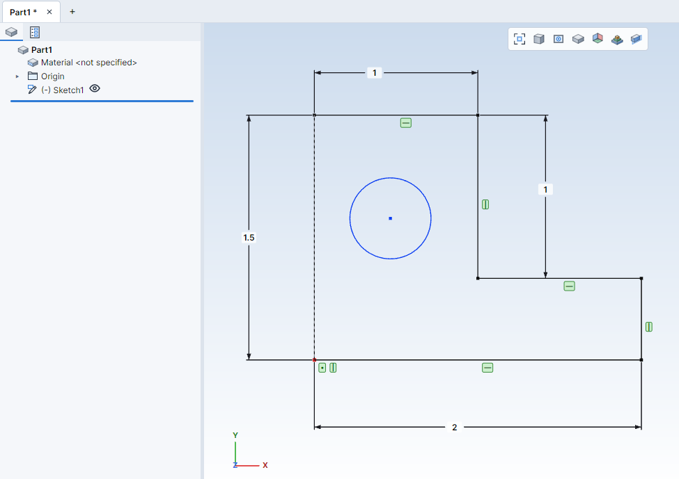
Construction geometry is drawn dashed. Geometry taken from the model or from another sketch is drawn dashed in purple.
The Sketch Page
The Sketch page is the sketch's own page. Its content depends on what is selected. The page is titled Hole Positions in a Hole position sketch, where only points can be drawn.
With Nothing Selected
- Status
- The sketch status, with the color key.
- Sketch Fillet
- Shown while Sketch Fillet is active. Radius sets the fillet radius.
- Polygon
- Shown while Polygon is active. Sides sets the number of sides, 3 to 64.
- Tools
- The single-key shortcuts, and Auto Arrange Dimensions. Dimensions you place or drag stay where you put them; the others are arranged automatically. Auto Arrange Dimensions rearranges all dimensions, or only the selected ones.
- Model Edges
- Convert Entities, which projects model edges and faces into the sketch.
- Sketch Axes
- Whether the sketch uses its plane's axes or is aligned to the model, and Sketch Axes…, which opens Sketch Axes. Not shown in a Hole position sketch.
- Pictures
- Sketch Picture…, and a row for each picture in the sketch with Edit and a delete button.
- Imported Geometry
- Import DXF…, and a row for each import in the sketch: a checkbox that locks or unlocks it, Select, Edit and a delete button. See Import DXF.
With a Selection
- Selected Entities
- The selected points, entities, relations and dimensions, up to 12.
- Add Relations
- A button for each relation the selection can take. See Relations.
- Existing Relations
- The relations of the selected geometry, each with a delete button. Fixed points show as Fixed, and converted geometry as On Edge.
- Options
-
- For construction
- Makes the selected entities construction geometry.
- Fix and Float
- Fix holds the selected points, and the endpoints of the selected geometry, in place. Float releases them.
- Auto Arrange Dimensions
- Shown when dimensions are selected. Rearranges their labels.
- Delete
- Deletes the selection.
- Parameters
- For a single selected point: its X and Y in the sketch, in the part's units.
- Dimension
- For a single selected dimension. See Dimension.
Selecting and Dragging
With no drawing tool active (press Esc), click geometry to select it and Ctrl + click to add to or remove from the selection. Drag in empty space to select the entities wholly inside the box, and the dimensions whose labels are wholly inside it.
Drag a point or an entity to move it. The geometry moves as far as its dimensions and relations allow. Dragging a circle's circumference changes its radius. Dragging a dimension's value moves its label.
A single point dragged, such as a line's endpoint, snaps as a point being drawn does and shows the same label (see Automatic Relations While Drawing). Released there, it takes that relation; a point dropped on another sketch point is Coincident with it. Horizontal, Vertical and inference lines are not applied. Hold Ctrl while dragging to move the point without snapping. A relation that would over-define the sketch is not added.
Model edges and faces can also be selected in a sketch, for Convert Entities, Sketch Axes and Normal To. Planes and sketches can be selected in the flyout design tree at the top left of the graphics area, for Normal To.
Automatic Relations While Drawing
As you draw, the pointer snaps to existing geometry and to the model, and a label beside the pointer names the relation the click will add:
| Label | Snaps to | Adds |
|---|---|---|
| Coincident | A sketch point or the origin | The point is shared, or Coincident with the origin |
| Coincident (model) | A model vertex | Coincident with a reference point at the vertex |
| Coincident (other sketch) | A point of another sketch shown | Coincident with a reference point at it |
| Midpoint | The middle of a sketch line | Midpoint |
| Midpoint (model edge) | The middle of a straight model edge | Midpoint on the edge |
| On line | A sketch line | Coincident on the line |
| On circle | A sketch circle or arc | Coincident on the circle |
| On edge (model) | A model edge | Coincident on the edge |
| Center (model) | The center of a circular model edge | Coincident with a reference point at the center |
| Horizontal, Vertical | Level or plumb with the previous point of a line or centerline | Horizontal or Vertical on the line |
A model edge or vertex snapped to is added to the sketch as reference geometry and follows the model when it changes.
Dashed inference lines also line the pointer up with the X or Y of sketch points, model vertices and circle centers. A point placed on one is Vertical (lined up in X) or Horizontal (in Y) with the point it lines up with, unless that would over-define the sketch. A faint dashed line joins the two points.
Construction Geometry
Sketch tab > Construction Geometry toggles the selected entities between normal and construction geometry. The For construction check box on the sketch page does the same.
Construction geometry is drawn dashed and is not part of any profile or path. Use it for reference lines, such as the axis of a revolve. A Centerline is a construction line.
Normal To
Sketch tab > Normal To, or press N or Ctrl+8. In a sketch it turns the view to look straight at the sketch plane. With a planar face selected, or a plane or sketch selected in the flyout design tree, it turns to that instead; with two, the first faces you and the second is at the top. Run it again to look from the other side. See Normal To for how the view turns.
Right-click a plane or sketch in the flyout design tree for Normal To and Show or Hide.
Sketch Keys
These single-key shortcuts work in the graphics area while a sketch is open:
| Key | Tool |
|---|---|
| L | Line |
| R | Corner Rectangle |
| C | Circle |
| A | Centerpoint Arc |
| S | Spline |
| P | Point |
| D | Dimension |
| T | Trim Entities |
| Esc | Ends the current operation, then returns to selecting, then clears the selection |
| Del or Backspace | Deletes the selection |
Right-click in the graphics area for the relations the selection takes, Select Midpoint on a line, the main drawing tools, Paste Picture, Exit Sketch and Discard Changes. View > Sketch Relations shows or hides the relation marks.
Sketch Tab Commands
| Command | Page |
|---|---|
| Sketch, Exit Sketch | This page |
| 3D Sketch, Exit 3D Sketch | 3D Sketch |
| Dimension | Dimension |
| Line, Centerline | Line and Centerline |
| Spline | Spline |
| Corner Rectangle, Center Rectangle | Rectangle |
| Circle | Circle |
| Centerpoint Arc, 3 Point Arc, Tangent Arc | Arcs |
| Straight Slot | Straight Slot |
| Polygon | Polygon |
| Point | Point |
| Trim Entities | Trim Entities |
| Extend Entities | Extend Entities |
| Sketch Fillet | Sketch Fillet |
| Offset Entities | Offset Entities |
| Mirror Entities | Mirror Entities |
| Convert Entities | Convert Entities |
| Construction Geometry | Construction Geometry |
| Add Relations | Relations |
| Sketch Picture | Sketch Picture |
| Import DXF | Import DXF |
| Sketch Axes | Sketch Axes |
| Normal To | Normal To |