Getting Started
Installation, documents, units, and a first part from sketch to fillet.
Installing
Download SpryCAD from sprycad.com. Builds are available for Windows 10/11 (64-bit) and Linux (x86-64), on two channels: Stable releases and Dev builds.
Windows
- Run the installer,
SpryCAD_setup_v<version>.exe. - If Windows SmartScreen shows Windows protected your PC, click More info > Run anyway. The installer is not code-signed yet.
- By default, SpryCAD installs for the current user and does not need administrator rights. To install into
Program Filesfor all users, select Install for all users when the setup asks. - Select the setup options. File associations for
.sprt,.sasmand.sdrware on by default. Open with for.step/.stpfiles and a desktop shortcut are optional. - Start SpryCAD from the Start menu.
For an unattended install, run the installer with /VERYSILENT /SUPPRESSMSGBOXES. To install for all users, add
/ALLUSERS and run from an administrator prompt. To uninstall, use Settings > Apps. Settings in
%APPDATA%\SpryCAD are kept.
Updates
Windows installs check for updates at startup and from Help > Check for Updates. When an update is available, select Update, Later or Skip This Version. After the download, select Install Now to restart SpryCAD with the update, or On Exit to install it when SpryCAD closes.
To change the channel or turn off the startup check, use Tools > Options > System Options > Updates.
Linux
| Package | Distributions |
|---|---|
.deb from the apt repository |
Debian 10+, Ubuntu 18.04+, Linux Mint 19+ |
.rpm from the dnf repository |
Fedora 28+, RHEL, Rocky or Alma 8+ |
Tarball (SpryCAD-<version>-linux-x64.tar.gz) |
Any distribution |
The download page gives the commands that add the apt or dnf repository for each channel. A repository install
updates with the other system packages. Start SpryCAD from the applications menu or with sprycad.
To install from the tarball, unpack it and run ./install.sh. The script installs SpryCAD into
~/.local/share/sprycad and adds a menu entry, the file types and the sprycad command. To update, run
./install.sh from a newer tarball. ./uninstall.sh removes the installation and keeps the settings in
~/.config/SpryCAD.
From Source
Install the .NET 10 SDK. From the repository root, run:
dotnet run --project src/SpryCad.App -c Release
Documents
| File | Contents |
|---|---|
.sprt |
A part: its features, equations, material and appearance |
.sasm |
An assembly: its components (linked part files or embedded parts) and mates |
.sdrw |
A drawing. See Drawings |
.step, .stp |
A STEP model. Opens or imports as a part, or opens as an assembly if the file holds one |
.stl |
A mesh. Opens or imports as a part |
Each open document has a tab below the command panel. See Document Tabs.
File Commands
| Command | Keys | Result |
|---|---|---|
| File > New | Ctrl+N | Creates a part in a new tab (Part1, Part2, …) |
| File > New Assembly | Creates an assembly in a new tab | |
| File > New Drawing… | Creates a drawing with one empty sheet | |
| File > Make Drawing… | Creates a drawing of the active part or assembly | |
| File > Open… | Ctrl+O | Opens parts, assemblies, drawings, STEP and STL files; accepts more than one file |
| File > Save | Ctrl+S | Saves the document; asks for a file name on the first save |
| File > Save As… | Ctrl+Shift+S | Saves the document under a new name |
| File > Close | Ctrl+W | Closes the active document; asks to save changes |
| File > Recent Files | Lists the files opened or saved last |
Open loads a STEP or STL file as a new document named after the file. Save then asks where to save it.
If another user has the file open, Open asks whether to open it Read-Only or Open Anyway. If another user saved the file after you opened it, Save offers:
- Merge…: merges your changes with theirs.
- Save as Branch: saves your changes as a branch to merge later.
- Overwrite: saves over their version. Their version is kept as a branch.
- Cancel
Import and Export
- File > Import… (Ctrl+I)
- Adds a STEP model or STL mesh to the active part as an Imported feature. The part embeds the file, so the part does not depend on the original. For an STL file, select millimeters or inches. Parts only: to use a model in an assembly, open it as a part, save the part, and insert it as a component.
- File > Export STEP…
- Writes the bodies as STEP AP214, with exact geometry and the part, face and feature colors. An assembly exports as a STEP assembly.
- File > Export STL…
- Writes the bodies as binary STL.
Exports are in millimeters. Cosmetic threads export as modeled threads, except on library parts such as fasteners. To model those too, turn on Model threads on standard parts in Tools > Options > Files.
Autosave
SpryCAD autosaves open parts. If SpryCAD stops abnormally with unsaved parts, the next start offers their autosaves:
| Button | Result |
|---|---|
| Restore | Opens the parts as last autosaved. The parts stay unsaved |
| Discard | Deletes the autosaves |
| Cancel | Keeps the autosaves and offers them again at the next start |
File > Recover Autosave… shows the same prompt at any time.
Units
Each part, assembly and drawing has its own unit system:
| System | Units |
|---|---|
| MMGS | millimeter, gram, second |
| IPS | inch, pound, second |
To change the unit system, click the units at the right of the status bar. For parts and drawings, you can also use Tools > Options > Document Properties > Units. New documents use the unit system set last.
The unit system sets how values display and the unit of a value typed without one. Changing it does not change the
model. A value typed with a unit keeps that unit: 10mm stays 10mm in an IPS part, and 10 is stored as 10in.
Values in different units can be combined, such as 1in + 2mm.
A First Part
- Click File > New (Ctrl+N).
- On the Sketch tab, click Sketch, then select Front Plane in the graphics area. The view turns normal to the plane. To skip this step, select a plane or planar face before you click Sketch.
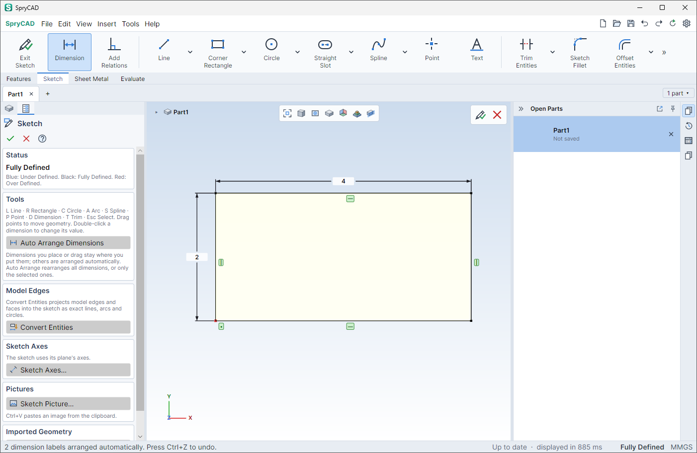
- Click Corner Rectangle (R). Click two opposite corners in the graphics area.
-
Click Dimension (D). Select a line of the rectangle, then click to place the dimension. Type the value and press Enter. Dimension the other side the same way. The status bar shows the sketch status: Under Defined, Fully Defined or Over Defined.
-
Click Exit Sketch, in the confirmation corner at the top right of the graphics area or on the Sketch tab.
-
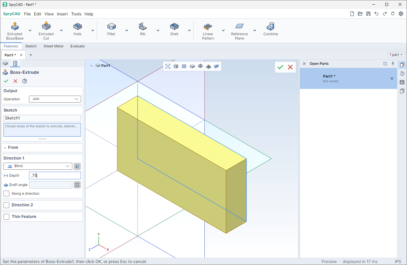
On the Features tab, click Extruded Boss/Base. The command uses the sketch you just closed. Set the Depth and press Enter. See Extruded Boss/Base.
-
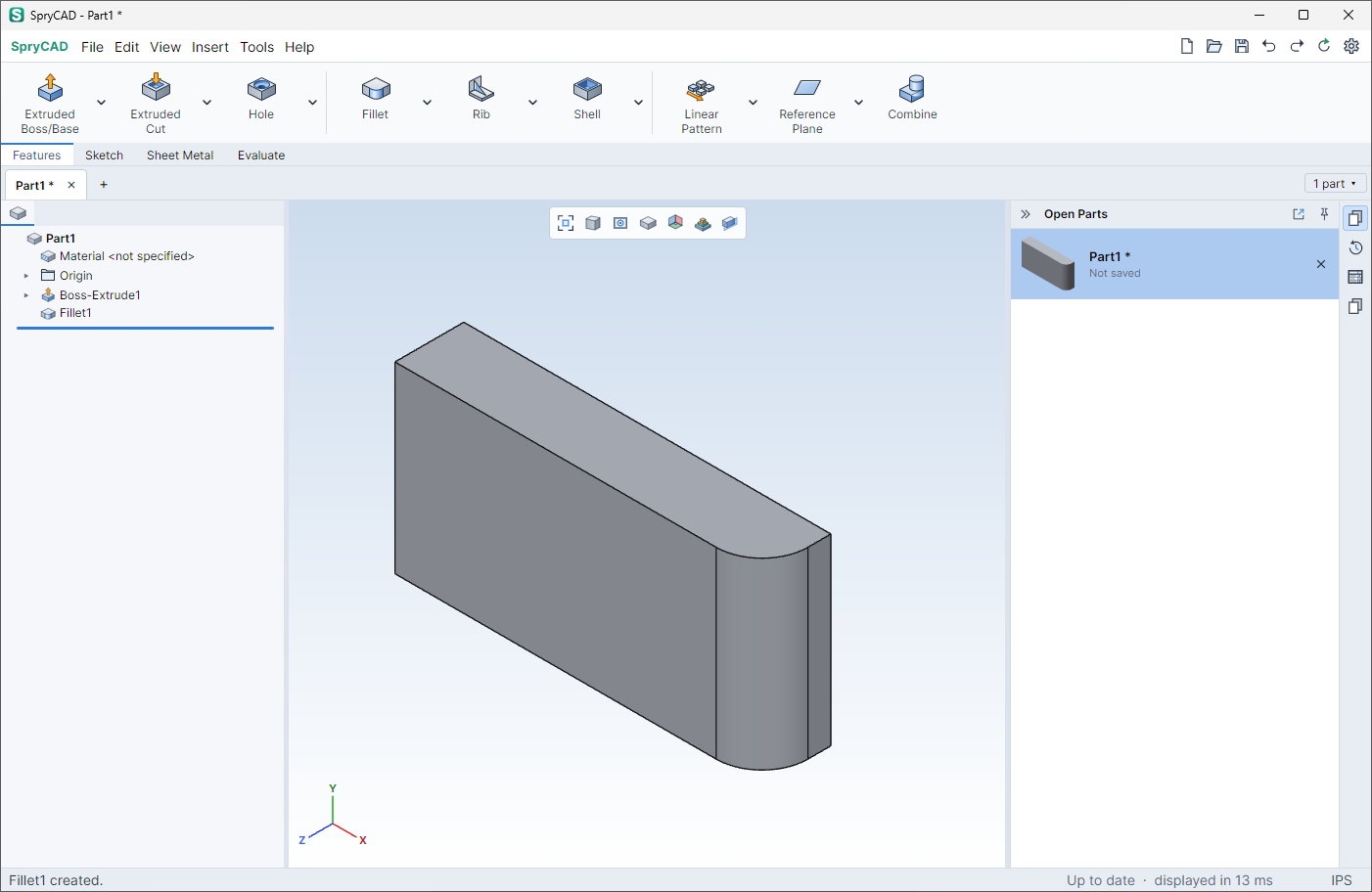
Right-click an edge of the box and click Fillet. Set the Radius and press Enter. See Fillet.
-
Press Ctrl+S and save the part as a
.sprtfile.
Sketch dimensions and property panel fields accept expressions and variable names, such as W/2 + 5mm. Type
L = 10 in a field to create the variable L and use it in that field. If L exists, the entry changes its value.