The Window
From top to bottom, the main window has the menu bar, the command panel and the document tabs. Below them are the design tree or property panel (left), the graphics area (center) and the task pane (right). The status bar is at the bottom.
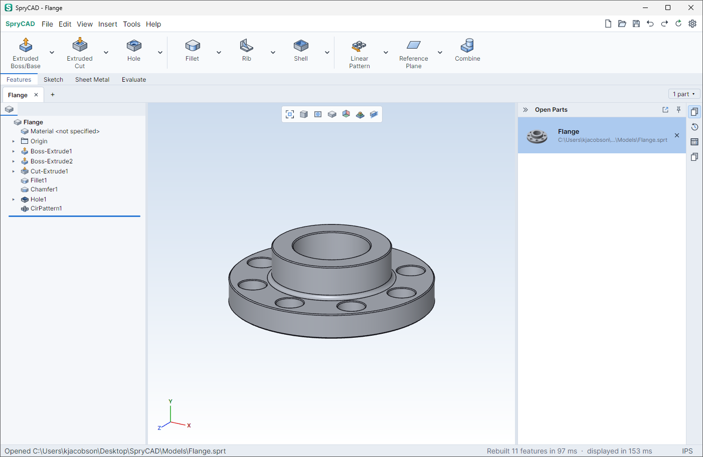
Menu Bar
| Menu | Items |
|---|---|
| File | New, New Assembly, New Drawing, Make Drawing, Open, Save, Save As, Save as Part (assemblies), Properties, Close, Recent Files, Import, Export STEP, Export STL, Save Image, Versions, History, Merge From, Recover Autosave, Exit |
| Edit | Undo, Redo, Delete, Rebuild, Force Rebuild, Suppress, Unsuppress, Roll to End |
| View | Orientation, Zoom to Fit, Problems, Display Style, Color by Feature, Section View, Perspective, Threads, Planes, Origins, Sketch Relations |
| Insert | Sketch, Boss/Base, Cut, Features, Pattern/Mirror, Reference Geometry, Sheet Metal |
| Tools | Parameters, Configure, Measure, Mass Properties, Edit Material, Appearance, Library Updates, Libraries, Add-ins, Options |
| Help | User Manual, Keyboard Shortcuts, Check for Updates, Change Log, Create Problem Report, About SpryCAD |
Part-only items, including the whole Insert menu, are unavailable in assemblies and drawings.
The right end of the menu bar has the New, Open, Save, Undo, Redo, Force Rebuild (Ctrl+Q) and Options buttons.
On a Mac, the menus are in the menu bar at the top of the screen. The SpryCAD menu has About SpryCAD, Check for Updates, Settings… (Options, Cmd+,), the standard Services and Hide items, and Quit SpryCAD (Cmd+Q). The Window menu, before Help, has Minimize, Zoom, Show Next Tab, Show Previous Tab and the open documents.
Command Panel
The command panel shows the commands of the selected tab:
| Tab | Commands |
|---|---|
| Features | Boss and cut features, Hole, Thread, Library Feature, Fillet, Chamfer, Rib, Split, Move/Copy Bodies, Scale, Shell, Draft, Move Face, Delete Face, patterns, Mirror, Reference Plane, Reference Axis, Combine |
| Sketch | Sketch, 3D Sketch or Exit Sketch, Dimension, Add Relations, the sketch entities, Point, Text, Trim and Extend Entities, Sketch Fillet, Offset, Mirror and Convert Entities, Construction Geometry, Sketch Picture, Import DXF, Sketch Axes |
| Sheet Metal | Base Flange, Convert to Sheet Metal, Edge Flange, Hem, Sheet Cut, Corners, Flatten, Export Flat |
| Evaluate | Measure, Mass Properties, Edit Material, Parameters, Design Table, Configure, Export STEP, Export STL |
| Assembly | The assembly commands. Shown only when an assembly is active. See Assemblies |
In an assembly, Evaluate has only Measure, Mass Properties and the exports. A drawing shows the View Layout, Annotation, Drawing, Sketch and Sheet Format tabs. See Drawings.
A command's tooltip gives its name, its single-key shortcut in a sketch if it has one, and what it does.
- Split buttons
-
Related commands share one button, for example Extruded, Revolved, Swept, Lofted and Helical Boss/Base. To list them, hover over the button, right-click it or click its arrow. Each listed command has its own tooltip. The button then shows the last command used, and clicking it runs that command again. In a sketch, the button shows the active tool.
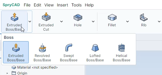
- More commands
- If the window is too narrow, the commands that do not fit go under » at the end of the row.
- Button size
- Right-click the command row and click Large Buttons or Compact Buttons, or use Tools > Options > View > Command Bar.
Document Tabs
Each open part, assembly and drawing has a tab. Each tab keeps its own view, design tree and undo history.
| Action | Result |
|---|---|
| Click a tab | Shows the document |
| Ctrl+Tab (Shift: back) | Shows the next tab. On a Mac, also Cmd+Shift+[ and Cmd+Shift+] |
| ✕ on the tab, middle click, Ctrl+W or Ctrl+F4 | Closes the document |
| + after the last tab | New Part or New Assembly |
| Right-click a tab | Close, Close Others, Close All, Copy File Path, Insert Into Assembly, Sort List By |
| Button at the right (Ctrl+E) | Lists the open parts in the task pane, with previews |
The button at the right shows the number of open parts, or +N more when tabs are hidden. In the list of open parts, the arrow keys move between parts. Type a part name to go to that part.
Design Tree
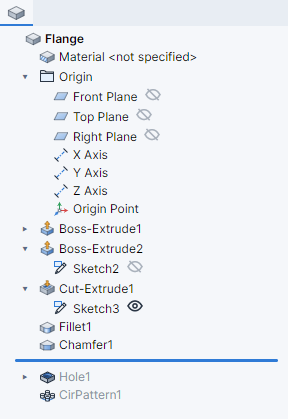
The design tree lists, from the top:
- The part and its material
- Spreadsheets, configurations and design tables, if the part has them
- The Origin folder: Front Plane, Top Plane, Right Plane, the X, Y and Z axes and the Origin Point
- The features and folders, in build order. A feature's sketch is under the feature.
| Action | Result |
|---|---|
| Click a row | Selects the feature. If a property panel page is open, adds the feature to the active selection box. Ctrl or Shift + click selects more than one |
| Double-click a row | Edits the feature or sketch |
| Right-click a row | Opens its menu, such as Edit Feature or Edit Sketch, Hide or Show, Suppress, Suppress When, Rename, Roll Back and Delete |
| F2 | Renames the selected feature or folder |
| Drag a feature | Moves it in the build order; a line shows the new position |
| Drag the rollback bar | Rolls the part back to that position |
| Eye on a sketch, plane or axis | Shows or hides it in the graphics area. The axes in the Origin folder have no eye |
Rows show these marks:
| Mark | Meaning |
|---|---|
| ✖ | The feature failed. The tooltip gives the reason |
| ⚠ | The feature has warnings |
| ƒ | The feature has a Suppress When condition |
| Time after the name | The feature took more than 200 ms to rebuild |
| (-) before a sketch name | The sketch is Under Defined |
| (+) before a sketch name | The sketch is Over Defined, or its solve failed |
Flyout Design Tree
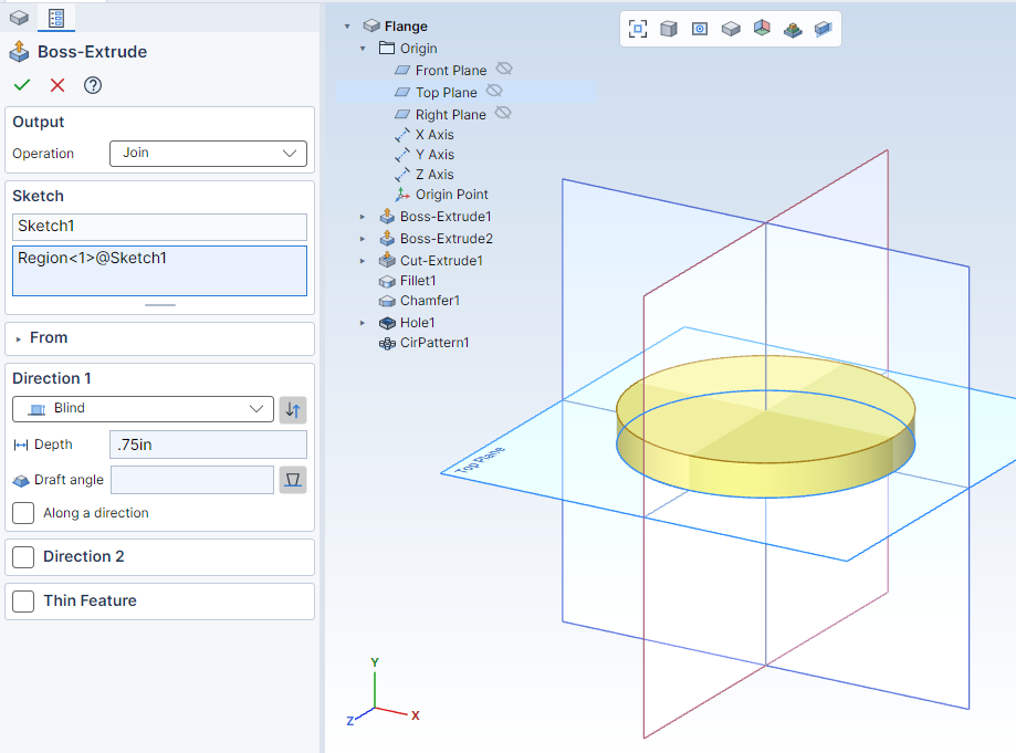
When the left panel shows a property panel page or a sketch, a copy of the design tree shows at the top left of the graphics area. In an assembly, it is the assembly tree. Drawings have no flyout.
Click the top row to expand the flyout. Features and planes selected in it go into the active selection box, as from the design tree. The eyes show and hide sketches, planes and axes. Right-click a row for the design tree menu.
In a sketch, Normal To turns to the plane or sketch selected in the flyout. The right-click menu then has only Normal To, Show and Hide.
Property Panel
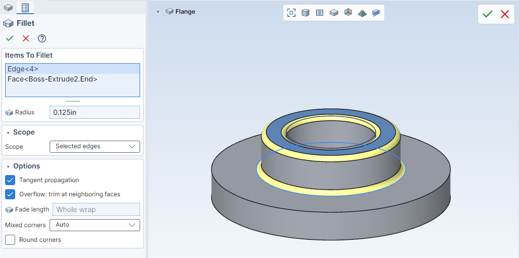
A command opens its page in the left panel, in place of the design tree. While the page is open, the panel tabs switch between the page and the design tree.
- OK and Cancel
- At the top of the page. OK (Enter) creates the feature or applies the change. Cancel (Esc) discards it. The confirmation corner in the graphics area has the same buttons.
- Help
- The Help button, next to OK and Cancel, opens this manual at the page's topic. The button shows only on pages that the manual covers. F1 opens the page's topic, or the manual's home page.
- Selection boxes
-
Lists of the geometry that a command uses. The active box is blue, and geometry selected in the graphics area or the design tree goes into it. Click a box to make it active. If the active box does not accept a selection, the selection goes into another box that does. To remove an item, select its row and press Del, or right-click the box and click Delete or Clear Selections. Boxes that hold more than one item have a grip below them for resizing.
- Messages
- Errors, warnings and hints show in a note next to the page, over the graphics area.
- Invalid values
- A field with a value that cannot be used turns red, and its tooltip gives the reason. If the feature fails with the values on the page, the last value typed turns red. OK does not accept a page with an invalid value. Correct the value, or press Esc to cancel.
- Values
- Length and angle fields accept a value with or without a unit, an expression (
W/2 + 5mm) or a variable name. A value without a unit is in the document units. The tooltip shows the result of an expression. Press Up or Down to change the value by 1 (Shift: 10, Ctrl: 0.1), in the unit the value uses. - Equations
- Type
L = 10in a field to create the variableLwith the value 10. The variable is created when you press Enter or leave the field, and the field then holdsL. Variable names are suggested as you type. Hover over a field with a variable to see its value. Double-click the field to open the variable in Parameters.
Graphics Area
- View toolbar
-
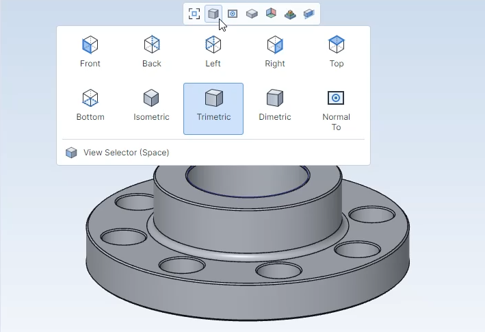
At the top center, in parts and assemblies: Zoom to Fit, View Orientation (which also has the View Selector and Normal To), Normal To, Display Style, Hide/Show Planes, Color by Feature (Color by Part in an assembly) and Section View.
- View Selector
-
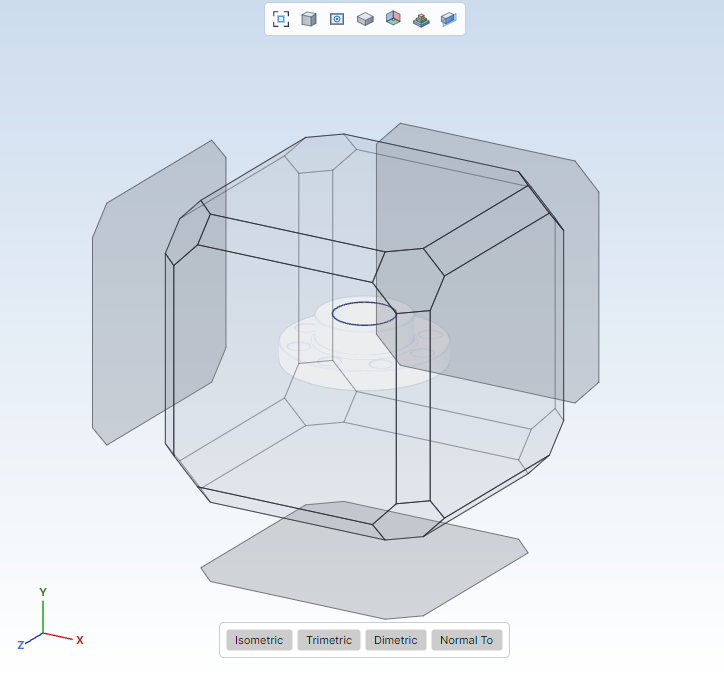
Press Space to show a box around the model, oriented with the view. Click a face, edge or corner of the box to view the model from that direction, zoomed to fit. Below the box are Isometric, Trimetric, Dimetric and Normal To. Esc closes the View Selector and restores the view.
- Mouse
-
Input Result Middle drag Rotates the view Ctrl + middle drag (Cmd on a Mac) Pans Shift + middle drag Zooms Alt + middle drag Rolls Wheel Zooms at the cursor Middle click on the model Sets the rotation center Middle click in empty space Resets the rotation center Middle double-click Zooms to fit By default the view rotates about the selected vertex, edge or face. Rotate about in Tools > Options
View changes this.
Without a middle button, Alt (Option on a Mac) with the left button replaces it: Alt + drag rotates, Alt+Shift + drag pans, Alt + click sets the rotation center and Alt + double-click zooms to fit.
- Keyboard
- F zooms to fit. The arrow keys rotate the view by 15° (Shift: 90°); hold one to spin the view. Ctrl + arrow keys pan, and Alt+Left / Alt+Right roll.
- Trackpad
- With Trackpad navigation on (Tools > Options > View, on by default on macOS), a two-finger scroll rotates the view, Shift + scroll pans, and a pinch or Ctrl + scroll zooms (also Cmd + scroll on a Mac). To swap scroll and Shift + scroll, set Two-finger scroll to Pans. On a Mac, a two-finger turn rolls the view. In a drawing, scrolling pans.
- Mouse gestures
-
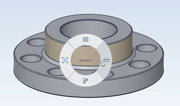
Hold the right button and drag to show a ring of four commands. To run a command, drag toward it and release, or drag through the ring. To cancel, release in the middle.
Mode Right Up Left Down Part Measure Normal To Zoom to Fit Sketch Sketch Dimension Circle Line Rectangle Assembly Mate Normal To Zoom to Fit Insert Components With Right-drag pans on (Tools > Options > View > Mouse, off by default), a right-button drag pans the view instead.
- Context menu
-
Right-click without dragging. The menu shows the commands for the item under the cursor:
Item Commands Planar face or plane Sketch, Hole (parts only), Normal To Sketch Edit Sketch, Change Sketch Plane, Extruded Boss/Base, Extruded Cut, Revolve Edge Fillet, Chamfer Cylindrical face or circular edge Select Axis, Select Center Face Face Appearance…, Feature Appearance… Assembly component The component's menu Empty space in a part Make Library Part… The menu then has Edit Feature and Edit Sketch for the feature that created the item, Measure, Zoom to Fit and View Orientation (Front, Top, Right, Isometric).
In a sketch, the menu lists the relations that the selection accepts, Line, Rectangle, Circle and Dimension, selection helpers such as Select Midpoint, Exit Sketch and Discard Changes.
- Context palette
-
When you select one item in a part, or an assembly component, a small toolbar with commands for it shows next to the cursor. The toolbar fades as the cursor moves away. It does not show while a page or sketch is open.
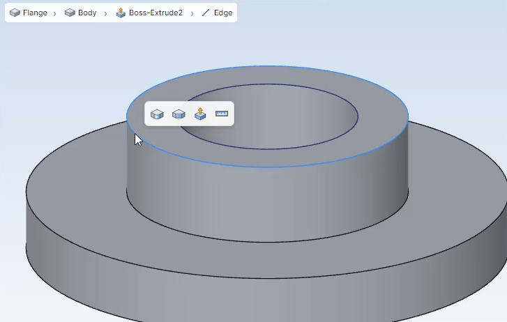
- Selection breadcrumbs
- When you select one face, edge or vertex in a part, a trail shows at the top left: the part, its body, the feature that created the item, and the item. Click the body or the feature to select it.
- Confirmation corner
-
At the top right while a page or sketch is open: OK and Cancel, or Exit Sketch and Discard Changes in a sketch.
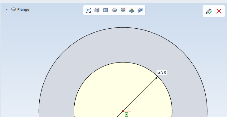
While the part rebuilds, Rebuilding… shows at the bottom right, with a progress bar and a button to cancel the rebuild.
Normal To
Turns the view to look straight at a plane. Press N or Ctrl+8, or click Normal To on the view toolbar, the View Selector, the mouse gestures, the context palette, the command palette, or the right-click menu of a planar face, plane or sketch.
- What it turns to
-
Selection Turns to A planar face, plane or sketch Its plane Two planar faces or planes The first, with the second at the top of the view Nothing, in a sketch The sketch plane Nothing, in a part The standard plane nearest the view: Front, Top or Right Nothing, in an assembly The origin plane selected in the design tree; otherwise the planar face of the next component you click (Esc cancels) Two parallel faces or planes are not accepted. Select a second one at an angle to the first.
- How the view turns
- By the smallest rotation from the current view. The view stays on the side of the plane it already faces, and the roll snaps to the nearest plane axis, so the view is square to the plane. Press Normal To again to view from the other side. Opening a sketch is different: it always shows the sketch from its front, with its X axis to the right.
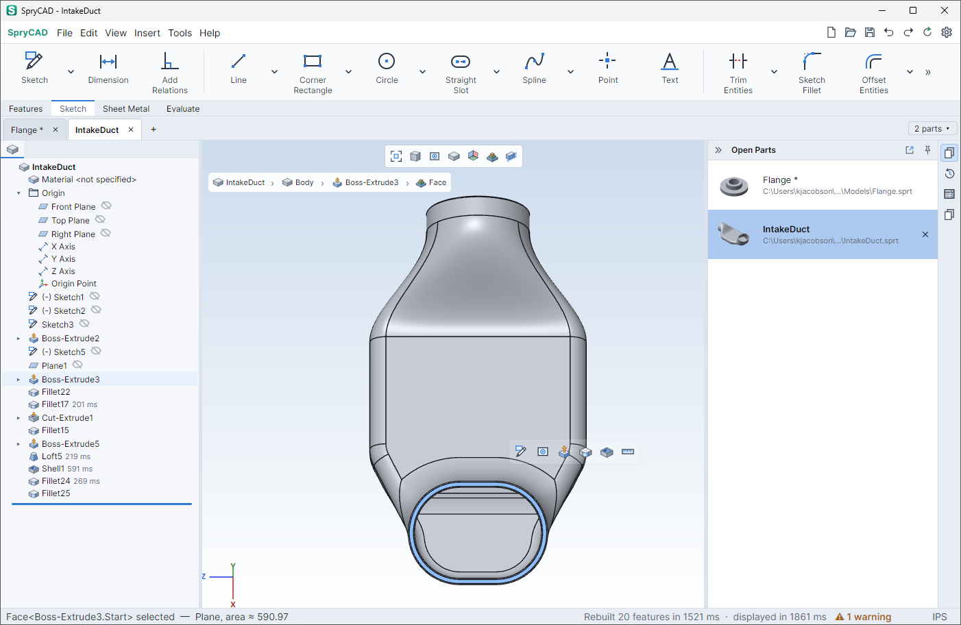
Task Pane
The strip at the right edge opens the task pane: Open Parts, Versions, Bill of Materials and Library. Drawings add View Palette, and add-ins can add their own panes.
The task pane slides out over the graphics area and closes when you click outside it or press Esc. Click the pin to keep it open beside the graphics area, or the pop-out button to open it in its own window.
Command Palette
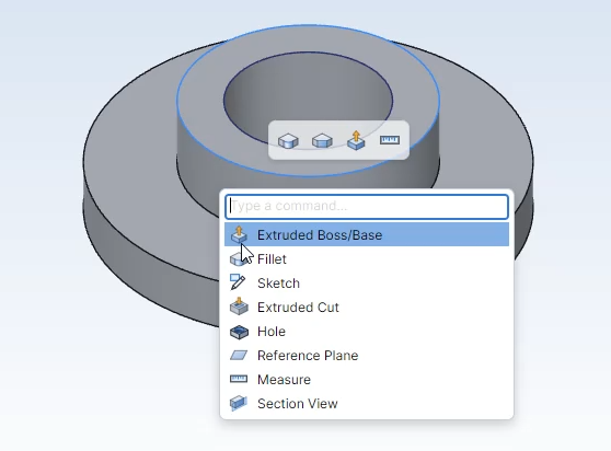
Press S to open the command palette at the cursor (not in a sketch or while a page is open). Press Ctrl+K to open it at the top of the graphics area in any mode.
With nothing typed, the palette lists the commands used most in this session, then common ones. Type words of a command name to find it. Up and Down select, Enter runs, Esc closes.
With no sketch, page or edit open, Enter runs the last command again.
Status Bar
From left to right:
- The last message, or the selection. A selected face shows its surface type and area; a selected edge shows its length or diameter.
- The last rebuild: the number of features rebuilt and the time.
- The number of errors, warnings and messages, if there are any. Errors count root failures only; the tooltip lists the dependent ones. Click to open the Problems list.
- Running add-in jobs, with progress and Cancel.
- In a sketch, the sketch status: Under Defined, Fully Defined or Over Defined.
- The unit system, MMGS or IPS. Click to change it.
Problems
The Problems list (View > Problems) shows each feature with an error or warning and its full message, then the commands that failed in this session. If a feature fails only because an earlier failed feature that it uses failed, the list puts it under the earlier feature and does not count it as a separate error. Fixing the first failure usually fixes the rest.
- Select a row to select the feature in the design tree and show its failed edges in red. This does not work while a page is open. Double-click the row to edit the feature.
- Root-cause rows have Edit, Suppress and Roll Back. Suppress also suppresses the features that use the failed feature, so the rest of the part rebuilds. Roll Back moves the rollback bar to just before it.
- Right-click a row for the same actions (Roll Back to Here) or to copy the row. Copy copies the whole list, and Clear Messages clears the failed commands.
When a feature newly fails or a command fails, a card shows at the lower right of the graphics area, unless the Problems list is open. The card names the first failed feature, not the features that fail because of it. When several features fail, it shows N Features Failed. The card has Edit Feature, Suppress, Problems and Dismiss. A feature card stays until you dismiss it or fix the feature; a command card stays until you dismiss it.
Help
Help > User Manual opens this manual in the browser, from the copy installed with SpryCAD or, if there is none, from sprycad.com. Help > Keyboard Shortcuts lists the shortcuts, with a search box. See Keyboard Shortcuts.